Network - Remote Devices
Please refer to the documentation supplied with the units for hardware details and installation instructions.
Connection
Remote Devices can only be connected using a Power over Ethernet (PoE) connection so a suitable PoE repeater or switch must be provided.
TCP/IP
Since the Remote Devices do not use TCP/IP, connection is more straightforward than with the Controllers, simply connect them to the network and use the thumb wheel on the device to set an Address, see Associating Remote Devices below.
Multicast
Remote Devices do however use a block of Multicast addresses for communication so these addresses must be available: 230.0.0.0, 230.0.3.1, 230.0.3.2 & 230.0.3.3. Please be aware that managed Ethernet switches which may block these addresses by default.
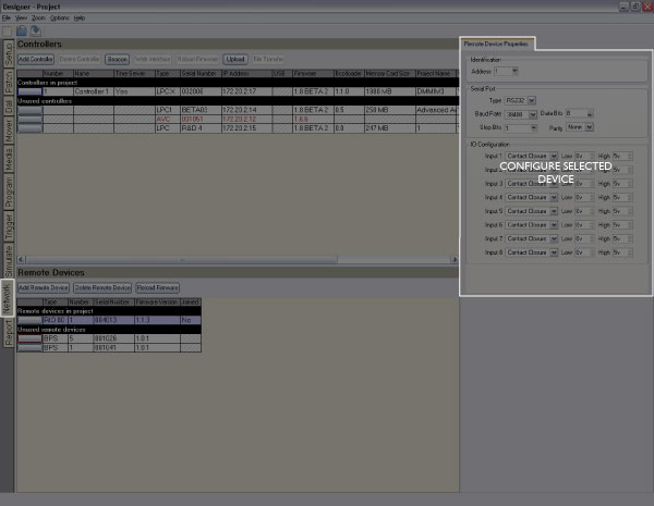
The bottom half of the Network window allows you to manage and configure any Remote Devices in the project and found on the network:
Project vs real Remote Devices
The list of Remote Devices is split into two sections: At the top is the list of project devices which may or may not be associated with real devices. Underneath is a list of all the unused real devices found on the network that have not been associated with project devices.
Managing project Remote Devices
To add and set the type of a project Remote Device:
- Press the Add Device button on the Remote Device toolbar
- In the Add Remote Device dialog, select the device type (RIO 80, RIO 44, RIO 08, RIO A, RIO D, BPS, BPI)
- Choose the device's number (the address selected on the device itself, see Associating Remote Devices below)
- Choose which controller the remote device should be associated with
- Press OK, the Remote Device will be added to the project (and associated to a real device if one of the correct type and address is found on the network)
To delete a project Remote Device:
- Select the project Remote Device by clicking the left hand button, the row will highlight
- Press Delete Device on the Remote Device toolbar
- The Remote Device will be removed from the project and, if no longer associated at all,the real device will move to the Unused list
Remote Device firmware
IMPORTANT: Remote Device may need to be updated if a new version of Designer software has been installed. Devices with incompatible firmware will be highlighted in red.
To update a Remote Device's firmware:
- Select the incompatible device by pressing the left hand button, the row will be highlighted
- Press Reload Firmware on the Remote Device toolbar
- The firmware update will proceed - you must not disturb this process
Associating Remote Devices
Unlike Controllers, which are uniquely associated with a project via their serial number, Remote Devices are associated by their address as selected on the unit itself. Fifteen automatic addresses (1>15) are provided with a manual option (M) for selecting more (16>100). Remote devices may share the same address and thus identity, useful for repeating a user interface at both ends of a corridor for example.
To associate a project Remote Device with a real device (automatic addresses 1>15):
- Select the project Remote Device by clicking the left hand button, the row will highlight
- Ensure that the device type and address matches a suitable unit, addressed at this number, found on the network
- The real device will move from the Unused list and fuse with the project device so completing the row details
To associate a project Remote Device with a real device (manual addresses 16>100):
- Ensure that the Remote Device is addressed to the "M" setting, you will need to note it's serial number (label on back)
- Select the project Remote Device by clicking the left hand button, the row will highlight
- Select the correct device type and the desired address in the range 16>100
- Select the Remote Device's serial number from the pull-down menu of devices found on the network
- The real device will move from the Unused list and fuse with the project device so completing the row details
Once all your project Remote Devices have been associated with real devices you can configure them, test your programming on the installation itself and finally upload to the Controllers for stand-alone operation.
Remote Input Output (RIO) device properties
Serial Port
The RIO 80, RIO 44 and RIO 08 have a multi-protocol serial port that can be configured to either RS232 full-duplex or RS485 half-duplex operation. The configuration options are:
- Type - select RS232 or RS485 as required
- Baud rate - select the baud rate
- Data bits - select the number of data bits (typically 8)
- Stop bits - select the number of stop bits
- Parity - select the parity type
I/O Configuration
The RIO 80, RIO 44 and RIO 08 differ by virtue of the number and type of I/O ports:
| RIO 80 |
Eight inputs, no outputs & serial port |
| RIO 44 |
Four inputs, four outputs & serial port |
| RIO 08 |
No inputs, eight outputs & serial port |
Inputs can be individually configured as either Contact Closure, Digital or Analog with the latter two modes allowing for the threshold or range to be selected. Outputs can be individually configured with a Startup state, whether the relay is on or off at startup.
See basic triggers for usage.
Audio
The stereo balanced line level audio input of a RIO A can be used for Audio triggers. Select the Audio button to enable this mode and to see the following configuration options:
- Route To - select the Audio Bus to route the incoming audio to
- Freq. Bands - select the number of frequency bands with which to analyse the incoming audio (max 30 per channel; the frequency bands sit along a logarithmic scale and have been chosen for an optimum response to music)
- Gain - turn Auto gain on or off, and set the manual gain level
- Peak Decay Rate - set the rate at which peaks in each frequency band will decay (the peak level can be used in triggers)
- Initially Enabled - the audio feed from a RIO A can be turned on or off by triggers, and here you can set the initial state
See advanced triggers for usage.
Timecode
The stereo balanced line level audio input of a RIO A can be used for timecode input. Select the Timecode button to enable this mode and to see the following configuration options:
- Channel - the audio input of the RIO A that the timecode input will be connected to
- Route To - select the Timecode Bus to route the timecode to
- Regenerate for - select the number of frames that will be generated by the RIO A's software flywheel in the event of a drop in timecode signal
- Ignore jumps for - select the maximum size of jump in incoming frames that will be ignored
MIDI
The RIO A has a MIDI input and output interface. This can either be used in Remote Device MIDI triggers, or it can receive MIDI timecode. The configuration options here are for MIDI timecode:
- Route To - select the Timecode Bus to route the MIDI timecode to
- Regenerate for - select the number of frames that will be generated by the RIO A's software flywheel in the event of a drop in MIDI timecode signal
- Ignore jumps for - select the maximum size of jump in incoming frames that will be ignored
DALI
The RIO D has a DALI bus interface. This can be used to control DALI ballasts via timeline programming or to receive DALI commands for use in DALI Input triggers.
Button Panel Station (BPS) device properties
Properties
The global properties for each BPS are set here:
- Minimum LED Intensity - set a percentage value as required, useful for ensuring that the buttons are always visible
- Held Timeout - set the amount of time in milliseconds that a button must be pressed to be considered as being held
- Repeat Interval - set the interval in milliseconds that a held button will transmit a repeat signal
Button Configuration
Each BPS has eight buttons with an integral white LED and the default setting for each button is set here:
- Effect - select the default LED effect (Off, Static, Slow Flash etc.)
- Intensity - set the default LED intensity (0% will equal the Minimum LED Intensity as set above)
See advanced triggers for usage and BPS learning IR for infrared operation.
Button Panel Interface (BPI) device properties
Properties
The global properties for each BPI are set here:
- Minimum LED Intensity - set a percentage value as required, useful for ensuring that the buttons are always visible
- Held Timeout - set the amount of time in milliseconds that a button must be pressed to be considered as being held
- Repeat Interval - set the interval in milliseconds that a held button will transmit a repeat signal
Button Configuration
Each BPI has sixteen buttons with a linked output designed to drive LEDs, the default setting for each output is set here:
- Effect - select the default LED effect (Off, Static, Slow Flash etc.)
- Intensity - set the default LED intensity (0% will equal the Minimum LED Intensity as set above)
 Related Topics